Tracks and roads: design and construction
Back to Tracks and roads
Choosing a route
Commonly, insufficient attention is given to road alignment in the design stage.
Alignment should carefully fit the natural features of the landscape to minimise construction difficulties, environmental impacts and cost.
Once the start and end points of a proposed road are determined, good aerial coverage should be used to plan the alignment. Seek a balance between route length, suitable grades and the avoidance of problem areas:
- keep to ridge and spur alignments as much as possible
- northern and western facing slopes are drier than southern and eastern slopes
- keep cross slope as low as possible to minimise earthworks
- keep away from drainage lines
- avoid swampy and boggy areas
- avoid sites of high flora and fauna values
- utilise natural benches, but avoid fossil landslips
- consider road safety, e.g. visibility around curves and at intersections
- size of vehicle to be carried
- road surface (earth, gravel or sealed)
- economics of cross draining associated with increasing slope
- soil erodibility (for earth roads). Gravelled minor roads are generally 10% maximum grade, with short stretches to 18%
- erodible materials require more frequent cross drainage, better batter stabilisation and control of dispersed materials in run-off.
- if necessary import crushed rock or surface gravel, even if only for difficult sections.
- At stream crossings decide whether culverts or a bridge are required.
- If a wetland or swampy area has to be traversed consider culvert capacity carefully, as the road will act as a flood retarding basin and can seriously affect the hydrology of the whole wetland system. Both normal flows and flood flows must be considered.
Minimisation of batters
Batters are the side slopes that connect the road surface to the contour of the surrounding land. At the completion of construction they are bare earth surfaces that can rapidly erode, so batter stabilisation is an important element of road construction.
The following issues are important:
- minimise batter slope length by avoiding steep cross slopes;
- batter slopes need to be kept under a critical maximum which depends on soil material (eg solid rock could take a 100% slope but sand only 25%);
- benched or stepped batters can be useful;
- complete batters at the time of benching the road; not after;
- leave a roughened (cultivated) batter surface to assist revegetation;
- spread top soil in critical areas where rapid stabilisation is required;
- revegetation is an imperative - use a spray mulch seeded with a cover crop or native seed to speed revegetation;
- protect the batter from flows of foreign water, use catch banks and drains;
- cater for any subsurface flows; and,
- watch-out for slumping and its effect on table drains.

Generalised road cross section showing cut and fill batters
Disposal of runoff from roads
Good drainage is essential to road stability, erosion control and road maintenance. The road surface must be kept dry and water transported away to rejoin the natural drainage system. Drains along the road edge (table drains) keep the road surface free of water. Water must be dispersed from the table drain across the batter to the broader catchment environment. Catchment drainage must be considered.
Catchment drainage
- keep the number of crossings to a minimum
- use culverts or bridges (avoid fords)
- properly assess peak flows for selection of culvert or bridge size and road approach design.
- do not align road adjacent to drainage line. Move decisively into and out of drainage line areas to minimize runoff water travelling directly into drainage lines.
- protect batters with catch-drains above.
- intercept subsurface flows where these seep from cut batters, and direct flow with safety to the table drain and then to culverts.
Table drains
These run along the uphill sides of the road to diectly collect runoff from the road surface and from batters:
- avoid ‘V’ shaped table drains, rather use broad based table drains to give lower water velocities and therefore lower shear forces and lower rates of erosion. However broad based table drains are a little more difficult to maintain, and the use of a rotary drain cleaner is preferred to a grader;
- design to allow for regular cleaning and grade maintenance
- give special care when constructing table drains in erodible soils.
Cross drains and offshoot drains
These drains disperse water collected in the table drains back into the catchment. On the up-hill side of the road water will have to be collected from the table drain and passed across or under the road in some form of cross drain, then discharged into an off-shoot drain. Aspects to consider are:
- culverts
- surface cross drains
- 'rolling-the-grade': modifying the surface grade to allow for cross drain construction.
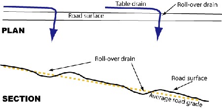
Rolling the grade for surface cross drains
- drop inlets are necessary - they need proper protection, otherwise headward erosion will move from them along the table drain above the culvert
- allow for cleaning of culverts (of leaf litter and sediment), by hand or by machine
- avoid discharging water at points with direct access to natural drainage lines and streams
- ensure overland flow moves through vegetation to reduce velocity and encourage infiltration
- may need energy baffles (eg hay bales, short diversion banks, rock beaching or special vegetation)
Velocity of run-off water
The aim is to prevent water reaching velocities, which will cause scouring of the particular soil materials. These velocities are set out in Table 1. Velocity increases as the flow increases. However velocity also depends on the gradient of the drain, its cross sectional shape and the surface condition, as well as the amount of water flowing down the drain. All other things being equal, the following hydraulic rules apply:
Occasionally it is worth calculating the velocity of run-off water from a particular road section (see below) and compare it to the scouring potential of the soil material. This will give working information to layout cross-drains to remove water before scouring velocities are reached.
Manning’s formula is used to calculate the velocity from table drain slope, its cross sectional area, and its hydraulic radius.
- V = (R0.67S0.5)n
Where
- V = mean velocity (metres/second)
R = hydraulic radius A/p where
- A is the area of flow (m2), and
p is the wetted perimeter(m)
N = Mannings roughness coefficient, which ranges from
- 0.04 for rock
to 0.01 for concrete
to 0.018 for earth and
to 0.018 for dense tall grass
- Roads need a well formed crown to get water off the road (300 mm height for a single track) and not allow water to move longitudinally down the surface of the road.
Maximum run-off velocities to avoid erosion
| Soil material | Maximum velocity |
| Sand | 0.3 m/s |
| 'Soft' clay | 0.3 m/s |
| 'Stiff’ clay | 1.0 - 1.2 m/s |
| Grassed surfaces | 2.5 m/s (for short periods) |
Road construction
Successful road construction depends on:
- careful planning, as above
- timing of construction - soils should be moist, not wet (when bogging occurs) or dry (when soils will not compact); road construction is a spring and summer job
- use of appropriate construction equipment
- sufficient compaction, and allowing a settling period before introducing heavy traffic.